Homework 5
Problem 1 (150 points)
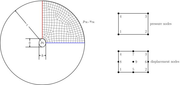
Consider a slightly asymmetric wellbore in an otherwise symmetric and homogenous medium in which the interior wellbore pressure $p_0$ is held constant. Assuming steady-state, plane-strain and undrained conditions, compute the displacements and pressures on the given mesh. The mesh information is provided in the following files with short descriptions of thier contents.
coords.csv - the geometric node locations for all nodes. They are listed in $x,y$ pairs with each line corresponding to a global node index starting with 1 and proceding in sequence.
connect.csv - the connectivity arrays. Each line contains the global node numbers of an element with local node numbering as specified in the schematic. For the pressue interpolates, only use the first 4 which will coorespond to the corners of the element.
nodeset1.csv - the nodes on the interior boundary. Use these nodes to specify the interior pressure, $p_0$.
nodeset2.csv - the nodes on the exterior boundary. Use these nodes to specify the far-field pressure, $p_{\infty}$.
nodeset3.csv - the nodes on the horizontal symmetric boundary (indicated in blue in the schematic).
nodeset4.csv - the nodes on the horizontal symmetric boundary (indicated in red in the schematic).
Assume zero fluid compressibility, i.e. $1/M = 0$ and the following dimensionless properties $\alpha = 1, \nu = 0.3, \mu = 1$ for Biot's coefficient, Poisson's ratio, and shear modulus, respectively. Apply an interior pressue $p_0=5$ and a constant far-field pressure $p_{\infty}=1$. Assume the far field boundary is stress-free as well. Create plots of the stress fields for $\sigma_{xx}$, $\sigma_{yy}$, and $\sigma_{xy}$ as well as the pressures.